UNIUS Ultrasonic Equipment
Situation
The high precision and longevity of technical components such as vessels, piping systems, turbine shafts, and vehicles in the automotive and aviation industry, is achieved in part by routinely performed preventative in-service inspections (ISI), preferably using non-destructive testing (NDT).
Powerful and intelligent ultrasonic testing systems are indispensable for ISI inspections. These systems should be usable for stationary, in situ applications and must be suited to the individual inspection task to ensure high inspection standards. In addition, they must be easy and quick to setup and use.
Solution
We provide standard and custom-designed ultrasonic equipment and components for a large variety of testing applications.
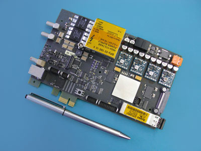
Fraunhofer IZFP's latest development UNIUS, a single channel ultrasonic Pulser/Receiver (P/R) Board can be easily integrated by ITK Software in customer GUI.
Q NET also provides UNIUS P/R Boards already integrated in ruggedized Notebooks for rough industrial environment which can easily be adopted to the customer's needs.
The receiver has ≥ 100 dB gain range and 0.1 dB resolution with 0.5 - 20 MHz bandwidth. The pulser is negative square wave 0-300V. For more details see section Technical Data.
Technical Data
| Number of transmitter channels | 1 |
| Pulse shape | Negative square wave |
| Pulse width | 30 ns to 800 ns, adjustable in steps of 12.5 ns |
| Pulse rise time | ± 2 ns (10% to 90% amplitude) |
| Pulse fall time | 20 ns ± 5 ns(90% to 10% amplitude) |
| Pulse delay | 0 ns to 17.89 s, resolution 4,17 ns |
| Transmitter voltage | Internal power supply: 0 V to 300 V programmable in 256 (1.17V) steps External power supply: up to 800V possible |
| Transmitter output impedance | 50 Ω, 300 Ω selectable by jumper |
| Pulse repetition frequency | ≤ 15 kHz [300 Ω, 50 ns pulse width, N23 ultrasonic reference standard] dependent on pulse width, pulse voltage, sampling rate, measurement range |
| Number of receiver channels | 1 (one connected to pulser [IE] and one separated [SE]) |
| Receiver input impedance | 50 Ω, 300 Ω selectable by jumper |
| Min. input sensitivity | 100 µVss |
| Max. input signal | 10 Vss |
| Input dynamic range | ≥100 dB |
| Receiver characteristic | Linear |
| Gain range | ≥100 dB, resolution 0.1 dB |
| TGC (Time gain control) Distance amplitude correction |
up to 256 values, equidistant time steps, min. time step width 1 µs; the usable range is full range minus gain; |
| Receiver bandwidth | 0.5 MHz - 20 MHz (-3 dB range) |
| Filter | 4 analog filters, fix 1 MHz (0.5 MHz – 2 MHz) / 2 MHz (1.2 MHz – 3 MHz) 4 MHz (3.2 MHz – 5.4 MHz) / 10 MHz (6 MHz – 14 MHz) / Bypass Optional 3 additional analog filters, pluggable |
| Operating modes | IE, SE |
| Receiver delay | 0 ns to 17.89 s , resolution 4.17 ns |
| A/D converter resolution | 14 Bit (13 Bit + sign) |
| Dynamic range A/D converter | ≤ 70 dB |
| A/D sampling rate | 240 MS/s |
| Time span resolution | 12,5 ns |
| Pulse fall time | 20 ns ± 5 ns(90% to 10% amplitude) |
| Acquisition delay | 0 - 53 s (32 bit) |
| Memory | Max. 128 k Samples (546 ìs at 240 MHz;1092 ìs at 120 MHz; 1638 ìs at 80 MHz; etc.) |
| Echo start gate (US_0) | 0 – 53 s, resolution 12.5 ns |
| (US_0 = surface) | Mode: threshold exceeding / gate end or fixed probe delay
0 – 53 s, resolution 12.5 ns |
| RF-Data |
Number of ranges: 1 Measurement range: 546 ìs – 34,9 ms, dependent on ADC-Sampling rate (scaling factor 1 - 64) Start measurement range: US_0 to 53 s, resolution 12.5 ns Data format: 16 Bit words (14Bit ADC-Data + overflow) |
| Average | Average of 2, 4, … 512 measurement results with pseudo random or fix time delay |
| Gates | Number of gates: 4 (overlap allowed) Measurement range: US_0 to 53 s, resolution 12.5 ns Data format: 16 Bit words (14Bit ADC-Data + threshold exceeding, 16 Bit runtime, resolution 12.5ns) |
| A-Scan | Number of ranges: 1 Sampling depth: 125, 250, 500, 1000 Pixel Sampling start: US_0 / SAP Measurement range: dependent on sampling depth and scaling factor (1-255) Data format: 16 Bit words (14Bit ADC-Data + Overflow) |
| TD-Scan |
Number of ranges: 1 Sampling depth: dependent on sampling depth of the HF-Signal Sampling start: dependent on sampling start of the HF-Signal Measurement range: dependent on sampling depth, sampling-rate of the HF-Signal and the scaling factor (2-256) Data format: 16 Bit words (14Bit ADC-Data+ Overflow) |
| Average | Average of 2, 4, … 512 measurement results with pseudo random or fix time delay |
| Trigger input | Coded CTP-trigger from coordinates unit, LVTTL, H- or L- active, pulse width > 100 ns |
| Digital I/O | 5 Input and 5 Output with ground |
| Extension connector | I/Os for possible extension boards |
| Communication and data | USB 3.0, standard Fiber- Optic interface on request (1500 Mbit) |
| Operating temperature | 5°C to 50°C |
| Form factor |
PCI Short Card (174 x 106,689) only mechanical support, Height of component side is with 20 mm out of PCI specification. Power supply from external connector. Additional mounting holes for stand-alone applications. |
| Power supply | 12V DC, approx. 1,1 A (≤ 13,2 W) |
WRITE TO US
Quality Network Pvt Ltd.
Works
No. 10, II Cross Street, Kalaimagal Nagar,
Ekkattuthangal, Chennai - 600032
CONTACT US
Registered Address
#38/GA, Shoreham, 5th Avenue, Besant Nagar,
Chennai – 600 090
CONTACT DETAILS
Phone: +91 44 3551 0355